Testing Optimization
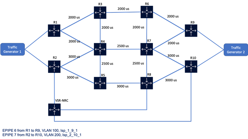
Figure 1. NSP Resource Control Network Diagram
Latency-based optimization
Step 1: Verify the prerequisites
- Verify that telemetry is enabled. Telemetry is enabled in this lab by default by a REST API call to the NSP which automatically enables four Kafka subscriptions ( IP, MPLS, LSP, LSP-path), verifiable by Insights Administrator application. The IPRC latency feature can accept 2 different sources of input. In this lab classic telemetry is used. Check if telemetry is enabled using REST API call GET v4/nsp/configuration/latency, more detail on the REST API call: https://network.developer.nokia.com/swagger/carriersdn-21-3.html/#/sdn-nrcp-configuration/getLatency
- Verify in the IP/MPLS Optimization application that latency is set on the links. In this lab static latency is set using REST API for all links.
- Path profile 30 is created with objective set to latency.
- Check the LSPs, in case LSPs are down, resignal the LSPs and they should be come up.
Step 2: Increase the latency of the path R1-R3-R6-R9 higher than 6500us using REST API
- Get the nodeID from the REST API request, GET /v4/nsp/net/l3/networks, more detail on the REST API call: https://network.developer.nokia.com/swagger/carriersdn-21-3.html/#/sdn-nsp/getNetworks2
- Using nodeID from the previouse REST response , get the termination point from the REST API request, GET /v4/ietf/te/node/{{nodeID}}, more detail on the REST API call: https://network.developer.nokia.com/swagger/carriersdn-21-3.html/#/sdn-ietf/getNode1
- Using the termination point from the previouse REST response , get the required linkUUID from the REST API request, GET /v4/nsp/net/l3/link/tp/{tpId}, more detail on the REST API call: https://network.developer.nokia.com/swagger/carriersdn-21-3.html/#/sdn-nsp/getLinkTp
- Using the linkUUID from the above REST response, increase the latency of the path R1-R3-R6-R9 higher than 6500us.
PATCH /v4/nsp/net/l3/link/{linkUuid}, more detail on the REST API call: ttps://network.developer.nokia.com/swagger/carriersdn-21-3.html/#/sdn-nsp/patchLink2
This postman collection can be used to increase the latency:
Latency Optimization postman collection
{
    "data": {
        "latency": 2700
        }
}
Step 3: Verify links and lsps in NSP
Once the latency values are increased and the total latency is higher than 6500us, lsp_1_9_1 will switch to path R1-R4-R7-R9 since this path now has the lowest latency.
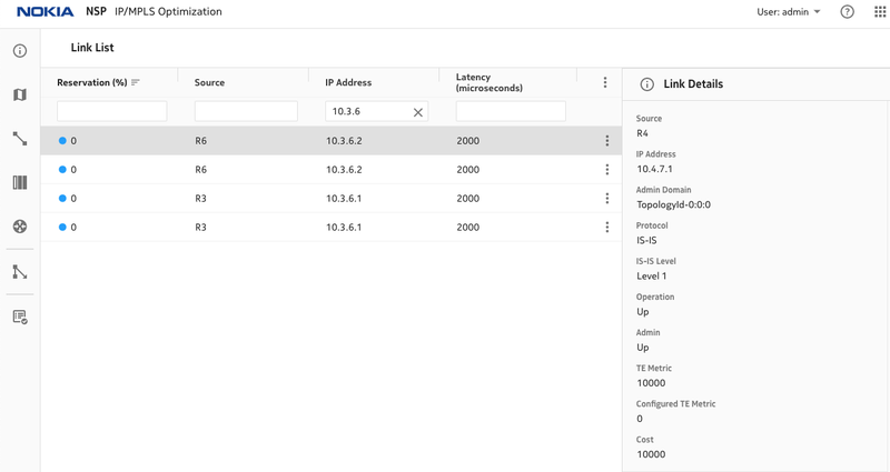
Figure 2. Latency on R3, R6 links
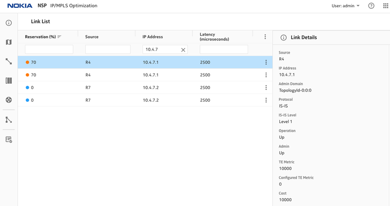
Figure 3. Latency on R4, R7 links
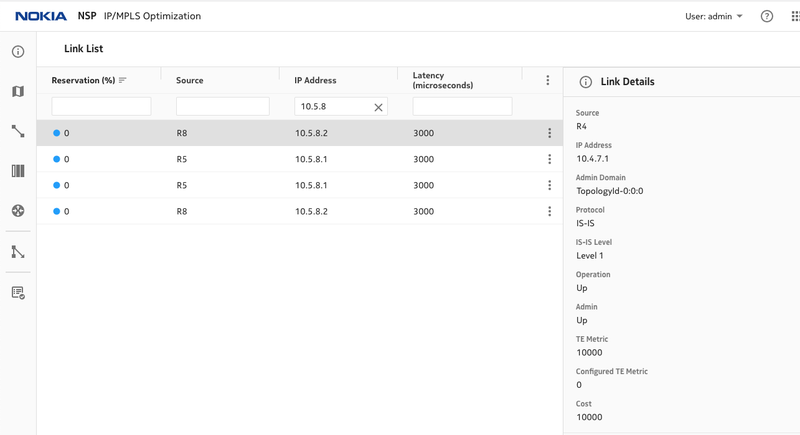
Figure 4. Latency on R5,R8 links
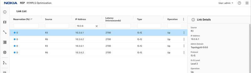
Figure 5, Latency is increased on R3,R6
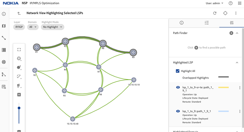
Figure 6. LSP paths before changing latency
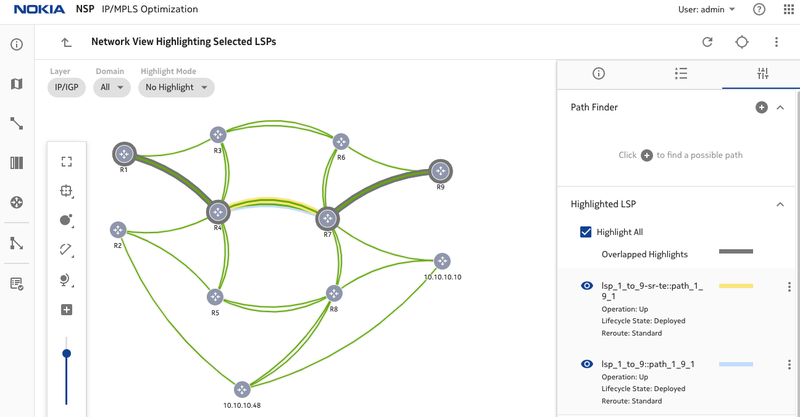
Figure 7. LSP paths after changing latency
Bandwidth-based telemetry optimization
Step 1: Verify Prerequsites
- Verify that traffic data collection is enabled in NSP. REST API request can be used to check if traffic data collection is enabled, GET /v4/nsp/configuration/traffic-data-collection/
more detail on the REST API call: https://network.developer.nokia.com/swagger/carriersdn-21-3.html/#/sdn-nrcp-configuration/getTrafficDataCollection
- Verify that 4 Kafka subscriptions required by IPRC (IP, MPLS, LSP, LSP-path) are created in Insights Administrator application and stats are collected from the 4 Kafka topics.
- Verify that 4 ACT rules (for IP, MPLS, LSP, LSP-path) are created. RESTCONF request can be used to check the ACT rules, GET /restconf/data/nsp-act:rta-act-rules. more detail on the RESTCONF call: https://network.developer.nokia.com/swagger/nsp-act-html-21-6.html/#
- Check the LSPs, in case LSPs are down, resignal the LSPs and they should be come up.
- Verify that the service EPIPE 7 is up.
Step 2: Start traffic generation
- SSH to the NFM-P, access TG2 and start the traffic receiver, ssh ossuser@192.168.100.51 (password: Ipsdnlab@sspa$$1%), iperf3 -s
- SSH to the NFM-P, access TG1 and start the traffic sender, ssh ossuser@192.168.100.50 (password: Ipsdnlab@sspa$$1%), iperf3 -c 10.1.200.4 -t 300 -b 3m
Step 3: Verify links and lsps in NSP
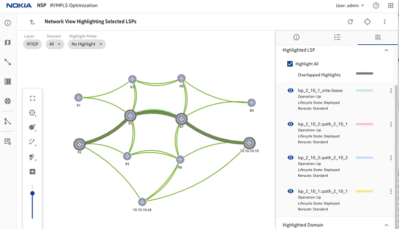
Figure 8. LSPs before traffic injection, lsp_2_10_1 is using path R2-R4-R7-R10
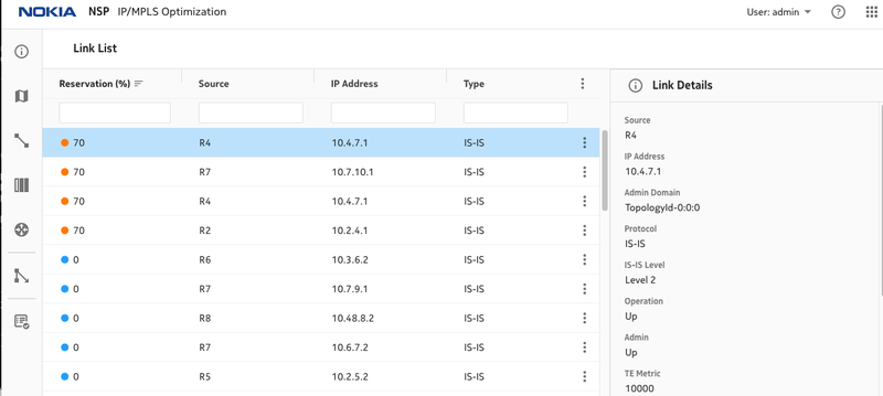
Figure 9. Link utilization Initially
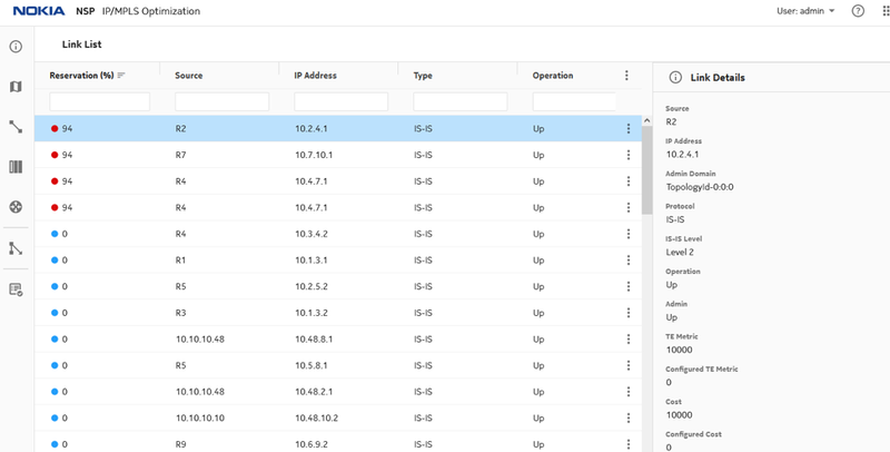
Figure 10. Link utilization at 94% after traffic injection
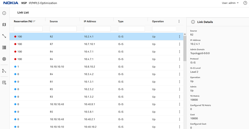
Figure 11. Link utilization at 100%
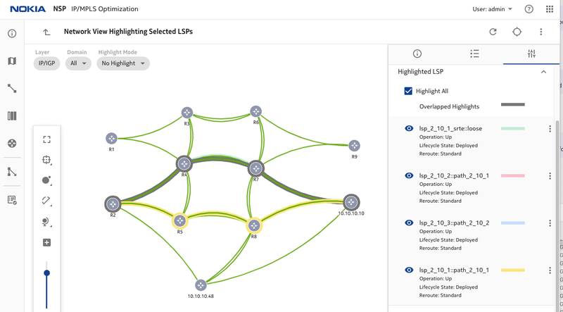
Figure 12. lsp_2_10_1 is rerouted to another path R2-R5-R8-R10
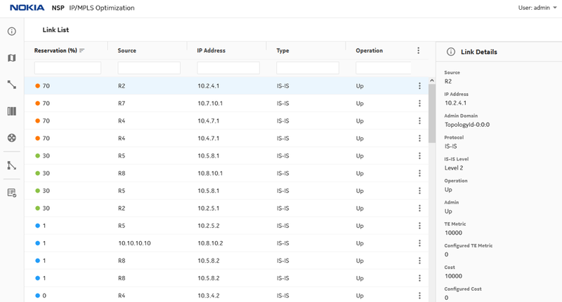
Figure 13. Link utilization after reroute
 /
/